Web servers, browsers, and proxies communicate by exchanging HTTP messages on a network structure using the request-response virtual circuit.
Web severs enable HTTP access to a collection of documents. And other information organized into a tree structure, much like a computer file system.
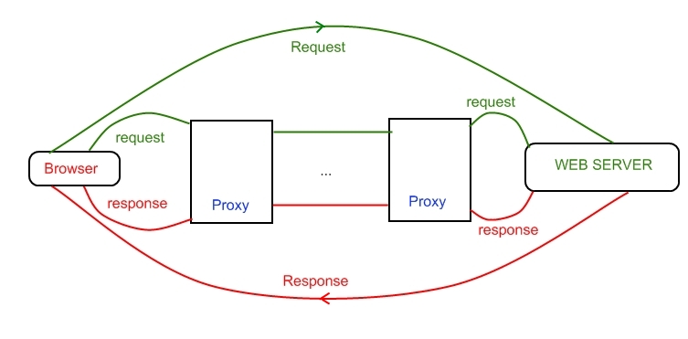
Web server receives and interprets HTTP requests from a client generally a browser. Then it examines the requests and maps the resource identifier to a file or forwards the request to a program which then produces the requested data. Finally, the server sends the response back to the client.
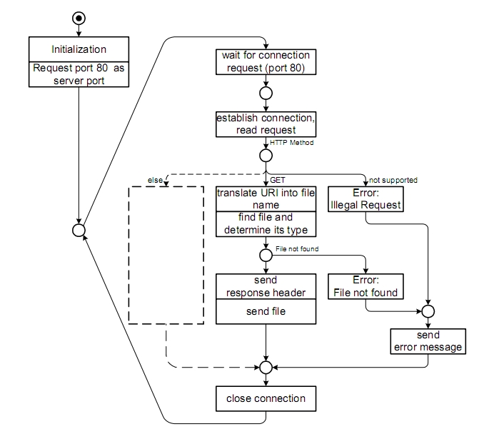
The behaviour of a single-tasking HTTP Server using the Petri Net1 formalism is shown in Fig. 2.
1 A Petri net consists of places, transitions, and directed arcs. Arcs run from a place to a transition or vice versa, never between places or between transitions. The places from which an arc runs to a transition are called the input places of the transition; the places to which arcs run from a transition are called the output places of the transition. More information is at link http://en.wikipedia.org/wiki/Petri_net.
WEB SERVER REFERENCE ARCHITECTURE
In this section we are going to show the reference architecture for web server domain. It defines the fundamental components of the domain and the relations between these components.
The reference architecture provides a common nomenclature across all software systems in the same domain, which allows:
-
to describe uniformly the architecture of a web server and to understand a particular web server passing before through its conceptual architecture and then through its concrete architecture, which may have extra features based on its design goals. For example, not all web servers can serve Java Servlets;
-
to compare different architecture by using a common level of abstraction.
The web server reference architecture proposed is shown in Fig. 3. As you can see, it specifies the data flow and the dependencies between the seven subsystems. These major subsystems are divided between two layers: a server layer and a support layer.
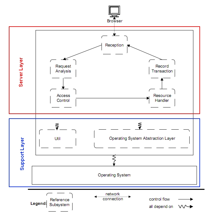
The Server Layer contains five subsystems that encapsulate the operating system and provides the requested resources to the browser using the functionality of the local operating system. We will now describe every subsystem of the layer.
-
The Reception subsystem implements the following functionalities:
-
It is waiting for the HTTP requests from the user agent that arrive through the network. Moreover it contains the logic and the data structures needed to handle multiple browser requests simultaneously.
-
Then it parses the requests and, after building an internal representation of the request, sends it to the next subsystem.
-
At the end it sends back the request’s response according to the capabilities of the browser.
-
The Request Analyzer subsystem operates on the internal request received by the Reception subsystem. This subsystem translates the location of the resource from a network location to a local file name. It also corrects typing user error. For example if the user typed indAx.html, the Request Analyzer automatically corrects it in index.html.
-
The Access Control subsystem authenticates the browsers, requesting a username and password, and authorizes their access to the requested resources.
-
The Resource Handler subsystem determines the type of resource requested by the browser. If it is a static file that can be sent back directly to the user or if it is a program that must be executed to generate the response.
-
The Transaction Log subsystem records all the requests and their results.
The support layer contains two subsystems that provide services used by the upper server layer.
-
The Utility subsystem contains functions that are used by all other subsystems.
-
The Operating System Abstraction Layer (OSAL) encapsulates the operating system specific functionality to facilitate the porting of the web server to different platforms. This layer will not exist in a server that is designed to run on only one platform.
There are two others aspects that characterize web server architecture and go in during its activity:
-
The processing model: it describes the type of process or threading model used to support a Web Server operation;
-
The pool-size behaviour: it specifies how the size of the pool or threads varies over time in function of workload.
The main processing models are:
-
-
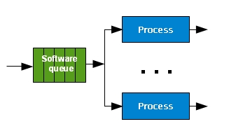
Process-based servers: the web server uses multiple single-threaded processes each of which handles one HTTP request at a time.
-
-
-
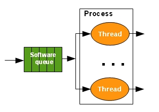
Thread-based servers: the web server consists of a single multi-thread process. Each thread handles one request at a time.
-
-
-
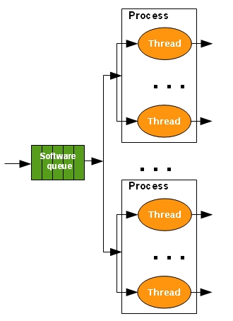
Hybrid model servers: the web server consists of multiple multithreaded processes, with each thread of any process handling one request at a time.
-
For the pool size behaviour we have two approaches:
-
Static approach: the web server creates a fixed number of processes and threads at the start-up time. If the number of requests exceeds the number of threads/processes, the requests wait in the queue until a thread/process becomes free to serve it.
-
Dynamic approach: the web server increases or decreases the pool of workers (processes and threads) in function of the numbers of requests. These behaviour decreases the queue size and the waiting time of each request.
Reception Subsystem: queue of requests and responses management
The Reception Subsystem maintains a queue of requests and responses to carry out its job within the context of a single continuously open connection. A series of requests may be transmitted on it and the responses to these requests must be sent back in the order of request arrival (FIFO). One common solution is for the server to maintain both an input and an output queue of requests. When a request is submitted for processing, it is removed from the input queue and inserted into the output queue. Once the processing is complete, the request is marked for release, but it remains on the Output Queue while at least one of its predecessors is still there. When the response is sent back to the browser the related request is released. Here is a code snippet using a C-like language to show how the queue of requests and responses are managed.
// DEFINITIONS

// UserRequest: represents the user request

// WebResponse: represents the relative web response

// DATA STRUCTURES

RequestQueueElement = (UserRequest, Marker);

ResponseQueueElement = (WebServerResponse, RelatedUserRequest);

// Requests that are not processed yet

Queue RequestQueueElement RequestInputQueue;

// Requests that are in processing or already processed

Queue RequestQueueElement RequestOutputQueue;

// Responses related to User Requests

ResponseOutputQueue; // FIFO politics

// ALGORITHM

While (true) {

If <User Request arrived> {

Enqueue(UserRequest, RequestInputQueue);

};

If <User Request can be processed> {

UserRequestInProcessing =

RemoveFrom(UseRequest,RequestInputQueue);

Enqueue(UserRequestInProcessing, RequestOutputQueue);

SubmitForProcessing(UserRequestInProcessing);

};

If <User Request has been already processed> {

MarkforRelease(UserRequest, RequestOutputQueue);

Enqueue(WebResponse, ResponseOutputQueue);

};

If <Length(ResponseOutputQueue)> 0 > {

WebResponse= Dequeue(ResponseOutputQueue);

RemoveFrom(WebResponse.UserRequest RequestOutputQueue);

SendResponse(WebResponse);

};

}
REFERENCES
[01] Andrea Nicchi, Web Applications: technologies and models, EAI, 2014;